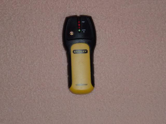
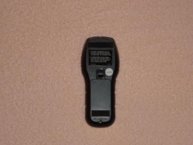
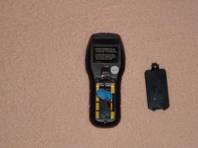
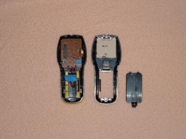
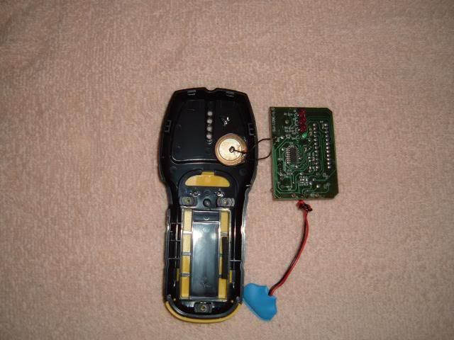
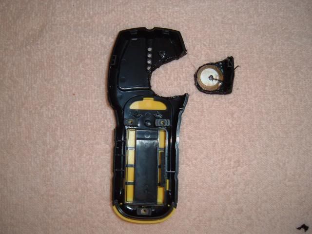
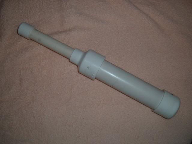
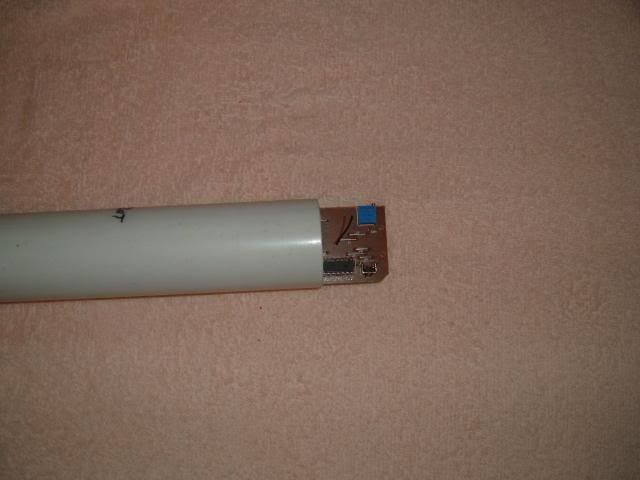
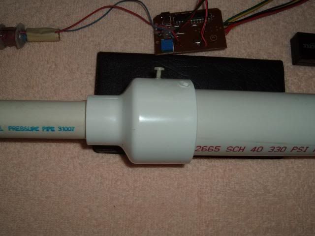
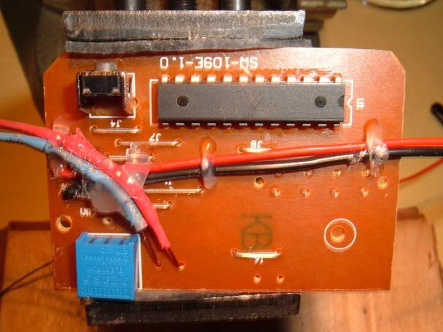
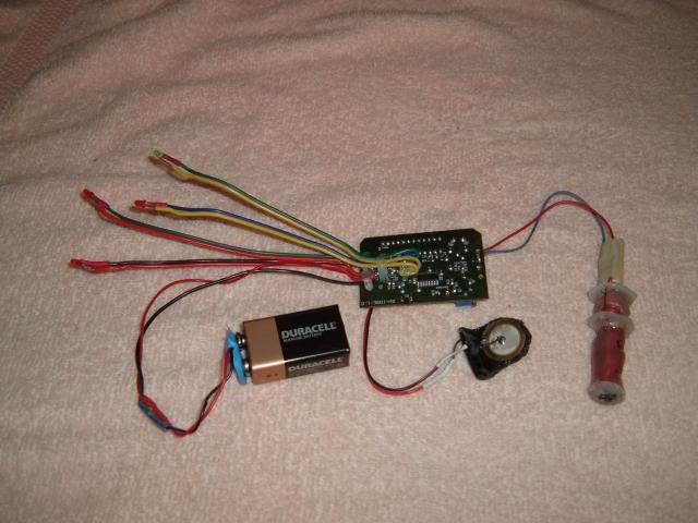
I have a Stanley Intellisensor stud finder that I'm modifying into a pinpoint.
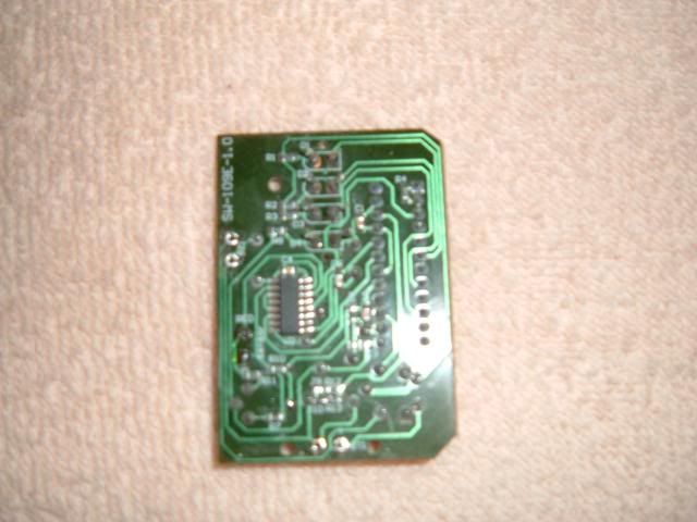
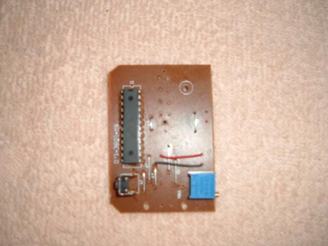
I opened it up and found the pickup is not a coil. It's a flat plate (etched circuit board) that has two areas on it. One is a small trace that goes around 3 of the outer edges and the other is a large square area that sits inside the smaller trace, like a square with a U around it. Each trace has only one wire connected to them (there is no connectivity between the two areas.) The small trace has a wire from the main board connected to the center of this trace. Like so ---I.
I made a few coils that didn't work.
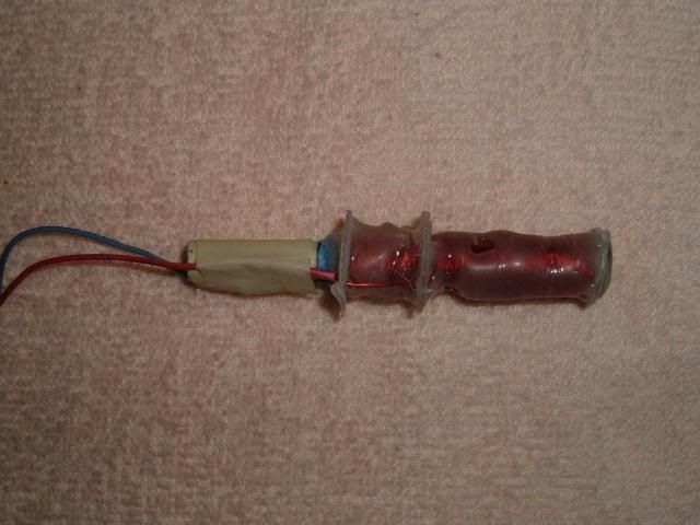
Here's two that did.
I measure the area each trace area covered. Then calculated how much .51mm enameled wire it would take to cover the same area.
The coils I made were both open ended (only one wire from each coil back to the main board.)
One was an air core coil and the other on a ferrite rod.
The bottom coil had 93" (add 8" extra for connecting to main board) of wire wrapped on a drinking straw or around a 4-5mm ferrite round rod (5mm x 100mm), this one connects to the red connection.
For the top coil I took 49" of wire, and soldered a 8" piece of wire at it's mid point, like in the rough drawing above (this wire connects back to the board (black.), when you wind this wire do it as if it's one length of wire. In other words when you get to the mid point just keep going.
The bottom coil covers about 1 1/4" of the core and the top coil covers about 3/4" of the core.
Yes - the wire overlaps it's self.
I found both the air and ferrite coils worked about the same. The ferrite coil may work out a little better.
You may have to readjust the sensitivity, do it 1/4 of a turn at a time.
The neater your wraps are, the better it will work.

