Find's Treasure Forums
Welcome to Find's Treasure Forums, Guests!
You are viewing this forums as a guest which limits you to read only status.
Only registered members may post stories, questions, classifieds, reply to other posts, contact other members using built in messaging and use many other features found on these forums.
Why not register and join us today? It's free! (We don't share your email addresses with anyone.) We keep email addresses of our users to protect them and others from bad people posting things they shouldn't.
Click here to register!
Need Support Help?
Cannot log in?, click here to have new password emailed to you
You are using an out of date browser. It may not display this or other websites correctly.
You should upgrade or use an alternative browser.
You should upgrade or use an alternative browser.
how to take off explorer housing from handle?
- Thread starter stasys
- Start date
sovereign-fan
New member
if anyone has ever striped one down i to would love to se some step by step pictures taken or is there a tutorial out there some were anyone knows of.
dippodigger
New member
not sure but I don't think I wold even want to try it.
sovereign-fan
New member
self repairs often save a lot of money.
John - Maryland
Member
Get a hold of Joe DeMarco. He's very good with these kinds of things.
See: http://www.findmall.com/read.php?63,1124949,1125922#msg-1125922
See: http://www.findmall.com/read.php?63,1124949,1125922#msg-1125922
Chris(SoCenWI)
Well-known member
I just had mine apart to reseat a couple of PC board connections-turning on the back light caused falsing and had to reconnect the ribbon connector to the display board. You'll need to remove the four screws that hold the two housing halves together, and I believe the cam lock also. Then you can remove the housing. I don't have mine right in front of me right now, otherwise I could explain in more detail. If you take apart the two halves of the handle assembly there you will find some of the wiring has been hot glued to on half or the other.
Not the best design in the world in my opinion. Reassembly can be a bit tricky- make sure you don't pinch any wires when you put the halves back together.
Chris
Not the best design in the world in my opinion. Reassembly can be a bit tricky- make sure you don't pinch any wires when you put the halves back together.
Chris
sovereign-fan
New member
at some point i am going to have to take my explorer xs apart as the earphone socket doesn't always work properly common fault i know.
 common fault i know.
If you need to work on the earphone jack to repair/replace, it only requires the 3 screws on the arm cuff/ hand/bat pod section and maybe remove the lower one on the handle section to allow you to open the two halves and be kept apart, a wedge of some description, without having to remove the control box.
Not too much involved and you might still be able to get the stock versions of the 3.5mm boxed in jacks or you can possibly hardwire a 6mm jack or the in it's place. There is the back rubber cover assembly to contend with , but it is quite simple.
david di
Not too much involved and you might still be able to get the stock versions of the 3.5mm boxed in jacks or you can possibly hardwire a 6mm jack or the in it's place. There is the back rubber cover assembly to contend with , but it is quite simple.
david di
and from memory it was being done at some stage toward the end of the production of the XS and/or when a repair was done and for the EX2.
Some of the guys who took to dismantling the Explorer XS's and EX2's found that the control box was actually glued on. There was one version that saw the conrol box being hacksawed of the handle.....hmmmm.
Great if it isn't glued, but in some cases it seems it was. There was some mention at the time that it seemed that superglue was used. I can understand why MAYBE a glue was used at this point as it seemed to make the EX control box handle section more solid when it was swung(never bothered me).
If it is superglued, then it's usually nothing that a bit of acetone can't dissolve. Maybe test the acetone on the Explorer plastic to ensure that it's not greatly affected by it. Maybe use some discretion and limit it when applying to the glued area to minimize the amount of "melting" that might occur.
sovereign-fan
New member
well guys i couldn't stand it any longer having a faulty earphone socket on my explorer xs so i took it upon myself to repair it.

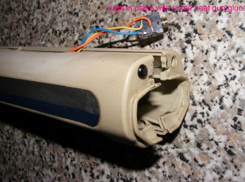
you only need to take out the first 3 screws from the battery flap back over to the hand grip to open up the shaft enough the get to the earphone socket. the socket is only held in place by some heat gun glue. removing the socket from the glue is the hardest part of the task.

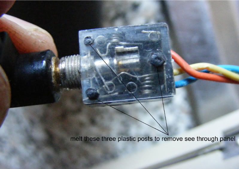
melt these 3 plastic posts to remove the see through panel. just reheat these again once your finished the repair or you can apply some glue to the posts to keep the panel in-place.

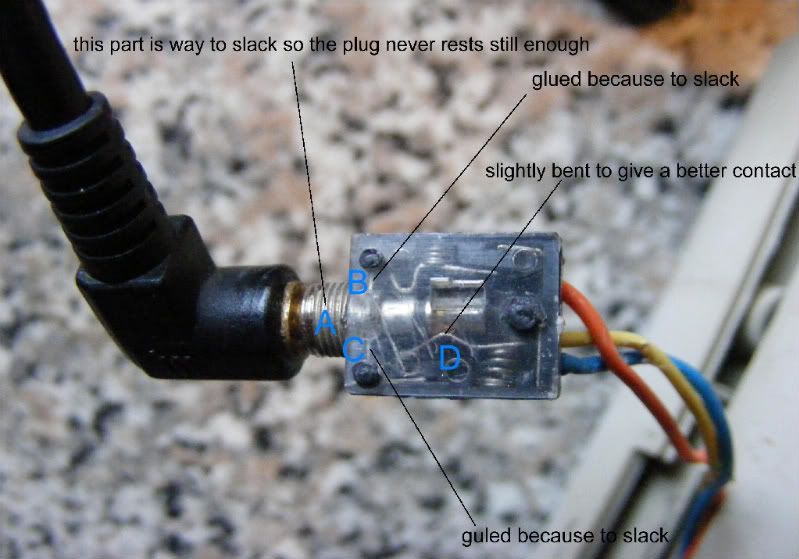
part A,B,C is actually one unit but is held in-place by the 2 metal lugs B&C the 2 lugs slide in to plastic slits. non of the plastic slits were broke but the unit was to slack so the plug would just move about instead of staying straight. the bottom spring barley moved some times when the plug was inserted in.
part A&B had glue applied to make the metal entrance hole more stable to stop movement of the plug.
part D i slightly arched the metal contact plate for a better contact because all of the plug movement from over the years of use had slightly altered the shape of the plate loosing good contact.

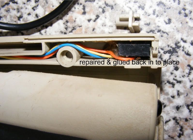
all the earphone parts were put back together and heat gun glued back in to its original place. job done and like new again.
i should of took a few more pictures during the process but it really is an easy fix.

you only need to take out the first 3 screws from the battery flap back over to the hand grip to open up the shaft enough the get to the earphone socket. the socket is only held in place by some heat gun glue. removing the socket from the glue is the hardest part of the task.

melt these 3 plastic posts to remove the see through panel. just reheat these again once your finished the repair or you can apply some glue to the posts to keep the panel in-place.

part A,B,C is actually one unit but is held in-place by the 2 metal lugs B&C the 2 lugs slide in to plastic slits. non of the plastic slits were broke but the unit was to slack so the plug would just move about instead of staying straight. the bottom spring barley moved some times when the plug was inserted in.
part A&B had glue applied to make the metal entrance hole more stable to stop movement of the plug.
part D i slightly arched the metal contact plate for a better contact because all of the plug movement from over the years of use had slightly altered the shape of the plate loosing good contact.

all the earphone parts were put back together and heat gun glued back in to its original place. job done and like new again.

i should of took a few more pictures during the process but it really is an easy fix.
Sorry to drag up an old thread but I'm wondering if anyone can help me with the wiring to the 3.5 mm headphone socket. I'm about to fit a new 3.5 mm socket to a Explorer XS but I'm having trouble understanding out how the headphones connect.
From the images above, it appears to me that there is no ground connection to the headphone's jack.
It appears that:
Orange - Centre pin
Yellow - Middle pin
Blue - N/C pin. This connects to the orange connection when the plug is out and open circuit when the jack is in.
Also, the ground pin on the 3.5 mm socket is cut off. Any help would be much appreciated.
So, you are wanting to go from a 3/8 to 1/4
You will probably not have room to fit it in there at-least years ago I was not able to find one that fit.
I just purchased a new 3/8 and put in a new one (purchased from Radio Shack).
Had to do the same to my hunting buddy's XS last year as the XS where prone to the Jack failing. That is one reason they went with a larger/stronger Jack on the XS-II.
Others went with what most here refer to as a Dongle on the XS to convert to a 1/4.
It is extending the cable on out through the hole using a 1/4 soldered into the 3/8 existing wires.
If you can find a 1/4 to that fits just hot glue it in that is how they came installed with the 3/8.
Here is a link that might help you.
Jack
Jack
Maybe this link might help you further.
1/4 Jack Diagrams
If you cannot get the information you need here go to search.
Type in Headphone Jack, Dongle, etc in the "Phrase" area
In the Forum category set it to the Explorer Classroom.
Then set the date time-frame to "all-dates".
Tones of information to be found.
Thanks for the reply MikeO.
Sorry I didn't explain myself very well. I recently purchesed a faulty XS which was missing the 3/8 socket. I want to fit a new 3/8 socket and have been searching the net for diagrams / instructions etc.
I came across this site and thought great, i'll use the images above to connect the three wires to the socket but when I looked closer, it appears that the ground or common connection is not fitted so I can't understand how the headphones will work.
Thanks for the links, I'll check them out.
The ones you get have extra lil tabs on them.
The one I used was this exact model pictured from Radio Shack I used to do my old XS and my friends current XS last year.
Be sure to read his last post it gives you what tabs to use.
It is about a 20 minute job max and it helps to have an extra pair of hands to help hold those tiny wires while you solder them.
Also, test it before you go hot glueing it all back together etc.
1/8 Jack Diagram
By the way I did not meen to type 3/8 in the other post I meant 1/8.

I'm borrowing a soldering iron from work tomorrow so I'll solder the wires to the pins shown in Johan's images.
But these diagrams are again confusing me. The pin out show that pin 1 is the common connection for the headphones but this is not used. I was just wondering how the headphones actually work without a common connection.
I haven't used a Minelab detector before. Am I missing something really obvious here. Can you use standard 1/8 headphones with a XS or are Minelab headphones wired differently?
Also, I wanted to mention all you have to do is remove the Arm Cup and the removed the screws around the Battery capsule area. No need to mess with the Headpiece.
There is some screws or one under the XS side sticker.
Very Carefully open it up. Use something to wedge in there to keep the two sides open.
You will first need to pick out the Hot-Glue before you will be able to get the 1/8 plug out
You will need a Hot-glue gun from a hobby shop to hold the new 1/8 in also..
Snip the wires as close as you can because there is not much left over to play with for sure.
As far as the Common I believe it makes contact on the inside.
I truly cannot remember but, I remember looking at the inside of the one I did last year and boy are they thin and cheap IMHO.
That is why they wore out so darn fast IMHO.
You can just pop the black cap of the defective one (only after you make sure you get they wiring down pat) and you will see what I am talking about.
I wish I had the pictures still I did back here in 2000 something but, most are no longer viewable.
I was shocked even to find the picture of the 1/8 for you.
Just follow those steps and you should be fine.
As stated Test before reassembly.
Thats all I can really add to what I have already posted.
Let me know how it works out.


